Shotbot
Stair-Climbing Delivery Robot
ShotBot is a stair-climbing delivery robot developed through Stanford Moonshot Club. I led the project from early concept development through mechanical, electrical, and embedded-system integration, culminating in a working prototype capable of controlled driving and stair traversal.
Explore the complete CAD, electrical design files, firmware, development footage, and technical documentation.
ShotBot uses a differential-drive tracked base with two articulated tracked front flippers. The main tracks provide propulsion while a separate worm-gear mechanism rotates both flippers together, allowing the robot to change its front geometry as it approaches and transitions onto a staircase.
Mechanical Architecture
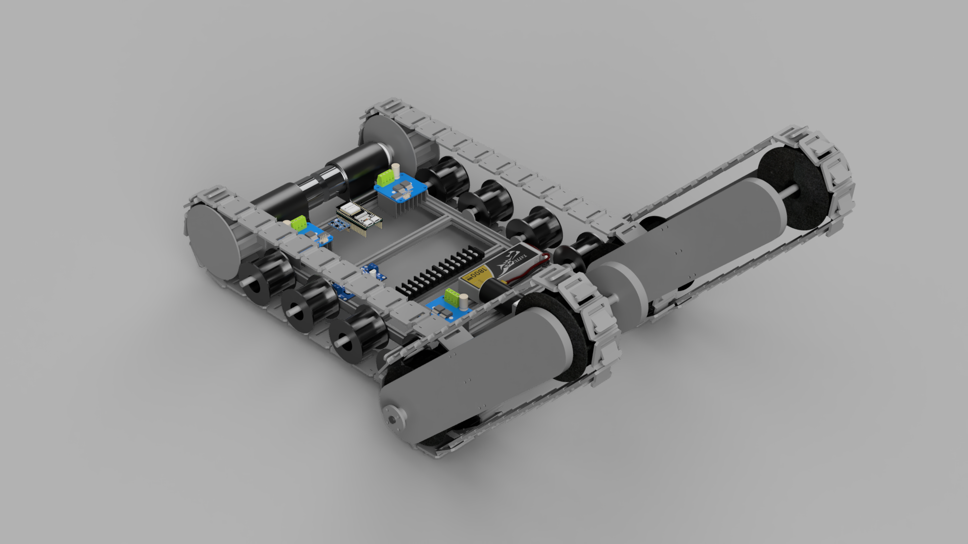
The stair-climbing mechanism required repeated physical iteration after problems emerged under full robot loads. Track-support components were redesigned several times to prevent excessive deflection, while drivetrain couplers and motor mounts were revised as testing exposed limitations in stiffness, torque transfer, and packaging. These iterations ultimately produced the configuration used in the successful stair-climbing prototype.
Electrical System
ShotBot is powered from a 3S LiPo battery with independently fused motor and control branches. Three BTS7960 H-bridges drive the left drivetrain, right drivetrain, and front stair-climbing mechanism, while an ESP32 provides the central control interface. The electrical system was first validated through breadboard-based integration before being consolidated into the final robot.
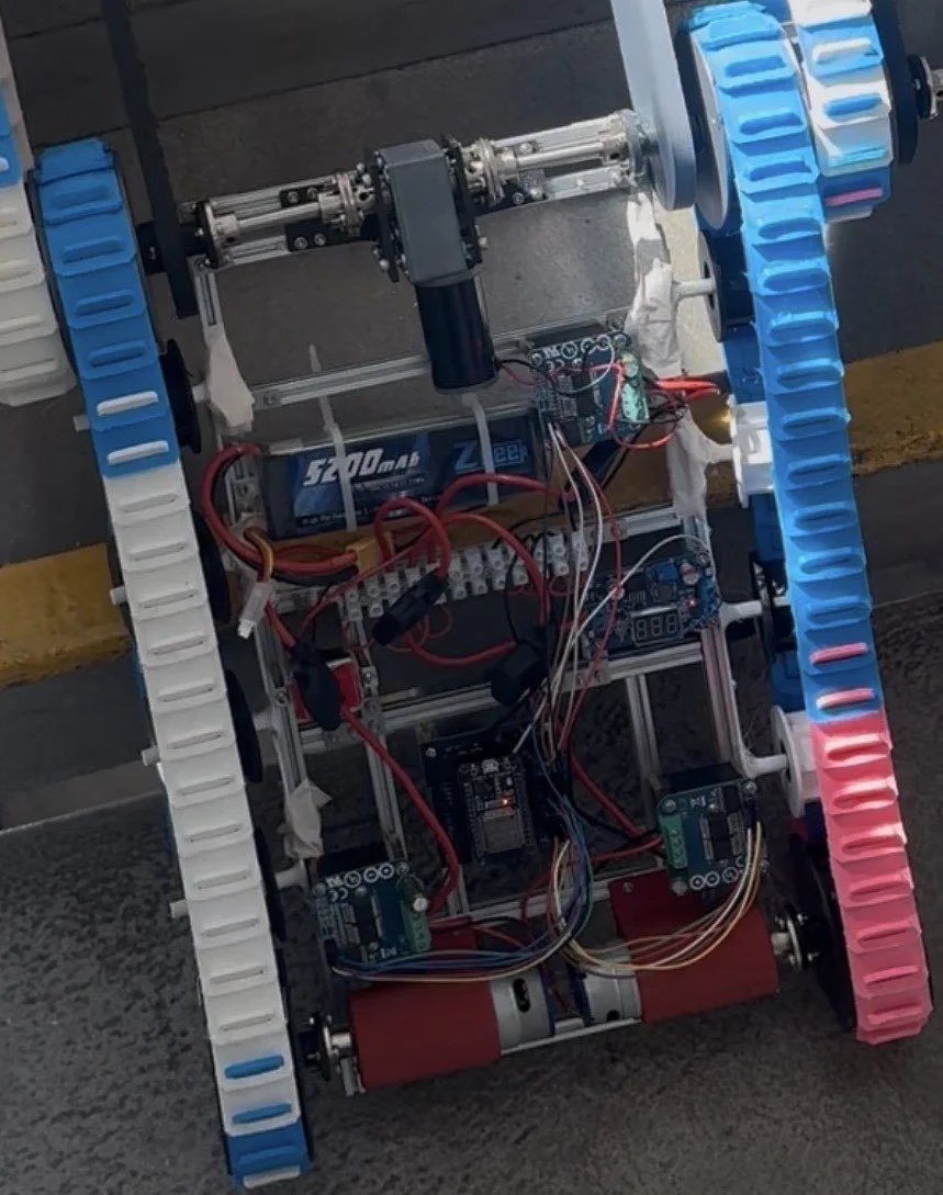
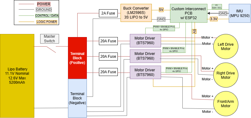
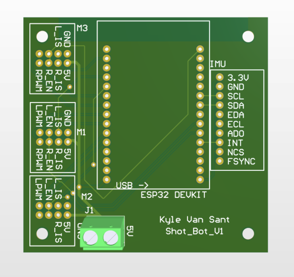
After validating the electrical system on a breadboard, the wiring was consolidated onto a custom PCB designed in Altium Designer. The board organizes the ESP32, motor-driver, IMU, and low-voltage interfaces, reducing point-to-point wiring and providing a cleaner, repeatable electrical implementation for the final robot.
The final robot is controlled by an ESP32 using a Bluetooth gamepad through Bluepad32. Independent joystick inputs provide tank-style control of the left and right tracks, while the articulated stair-climbing mechanism is controlled separately. The firmware also implements output limiting, joystick deadzone handling, and automatic motor shutdown if the controller disconnects.