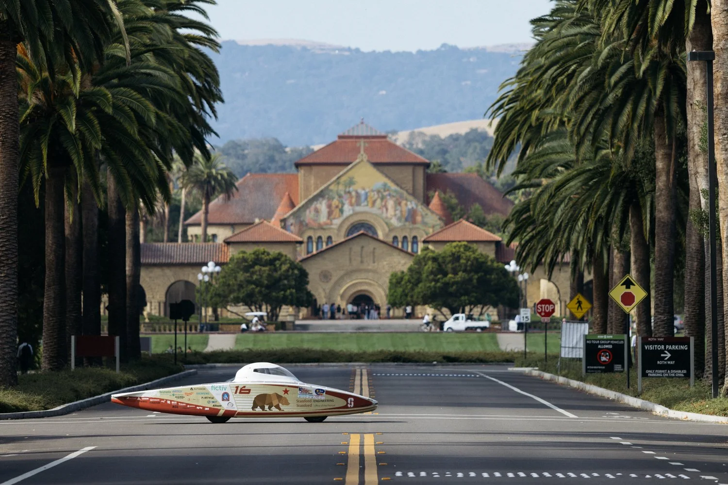
Stanford Solar Car Project
Electrical Systems & PCB Design
Stanford Solar Car is a student engineering team that designs and builds solar-powered race vehicles. I contributed to the electrical team through PCB design, routing, and vehicle integration work, supporting the electronics used throughout the car’s power and control systems.
Electrical System
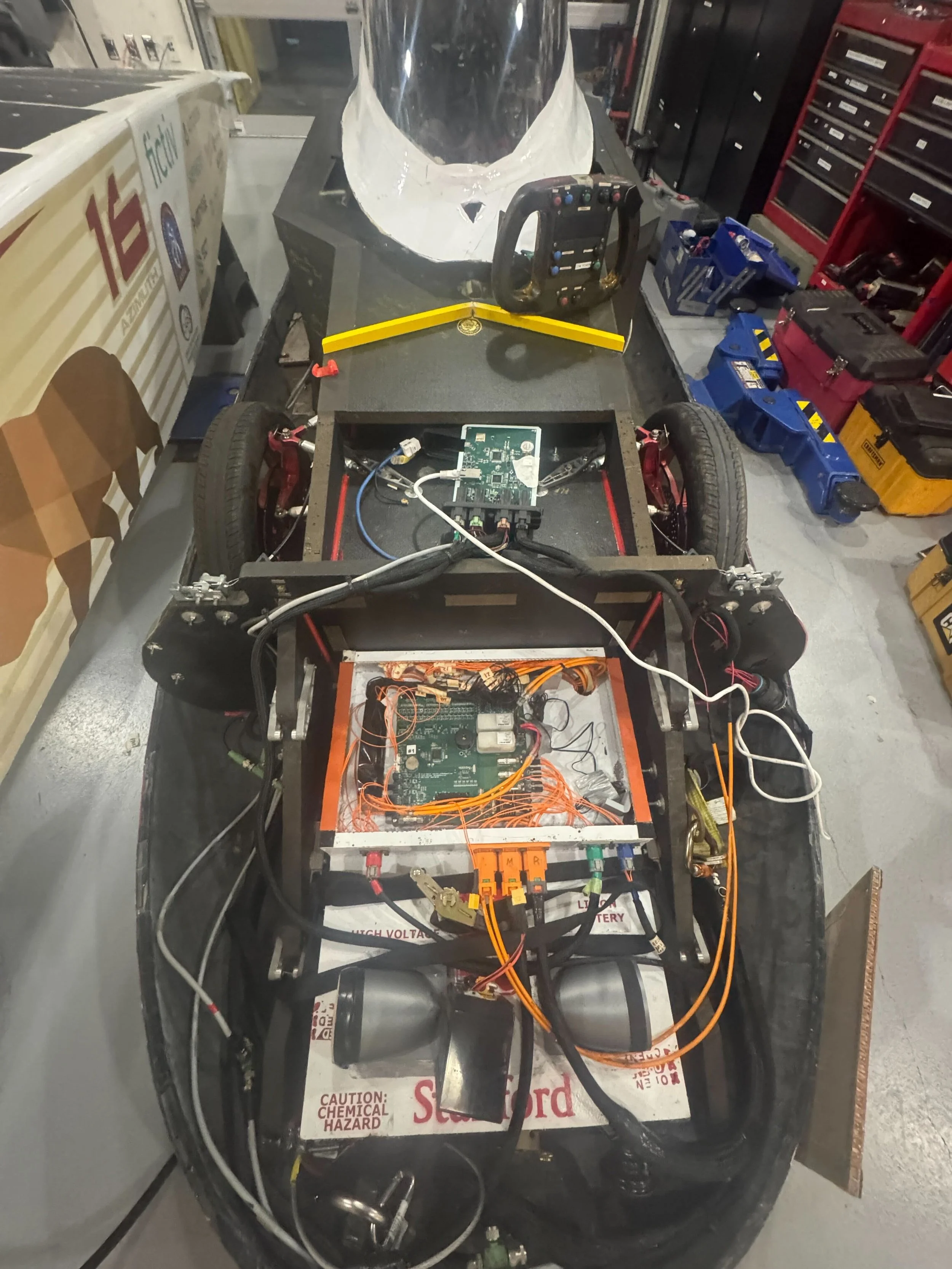
The solar car’s electrical system links the solar array, high-voltage battery, BMS, and vehicle computer into a coordinated power and safety architecture. Energy from the array is managed into the battery pack, while the BMS continuously monitors cell voltages, temperatures, and pack conditions to keep charging and discharging within safe limits. The vehicle computer ties the major subsystems together, handling communication, telemetry, and fault monitoring so that problems in the battery, power electronics, or other electrical systems can be detected and responded to before they create a risk for the driver.
Motherboard & Vehicle Control Architecture
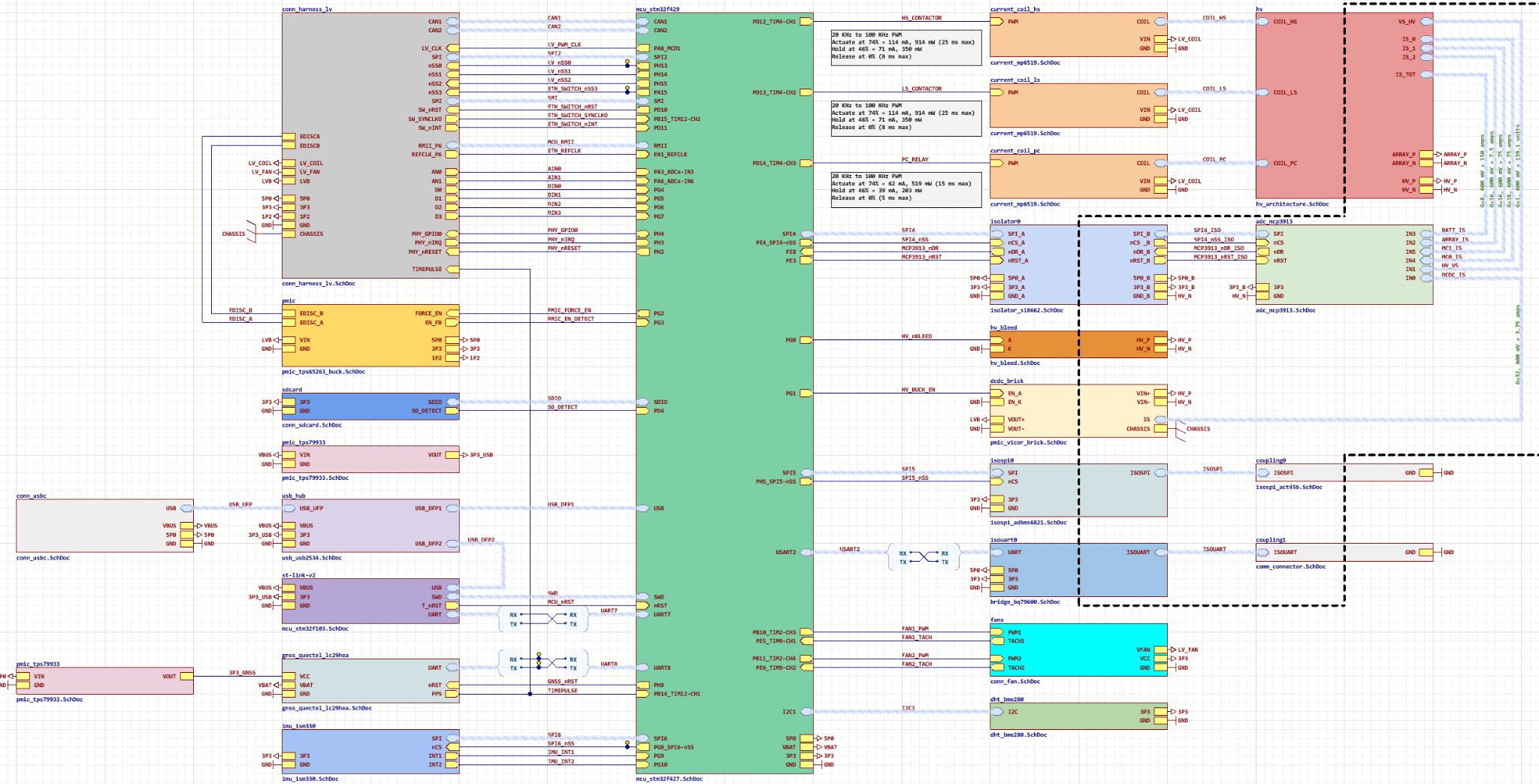
The upcoming car uses a custom six-layer motherboard as the central interface between the car’s control, safety, sensing, and communication systems. Built around an STM32F429 microcontroller, the board interfaces with the vehicle CAN networks and coordinates critical functions including high- and low-side contactor control, precharge, high-voltage bus monitoring, current sensing, and system shutdown behavior. Isolated measurement circuitry monitors currents from the battery, array, and motor-controller paths, while additional interfaces support low-voltage power conversion, IMU and GNSS sensing, SD logging, USB, and other vehicle peripherals. Together with the BMS and solar-array electronics, the motherboard allows the vehicle computer to supervise the high-voltage system and respond to unsafe conditions before they can threaten the battery, power electronics, or driver.
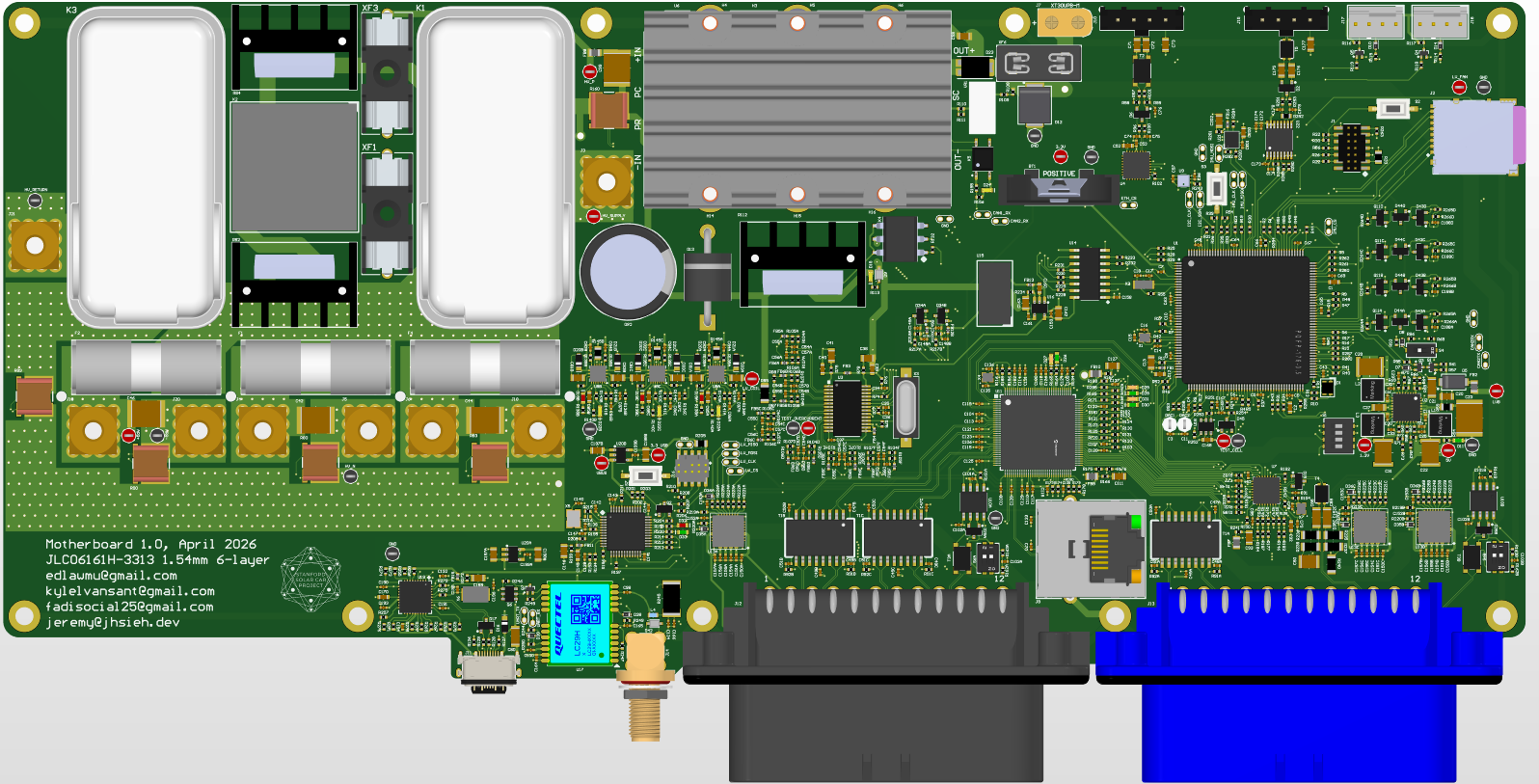
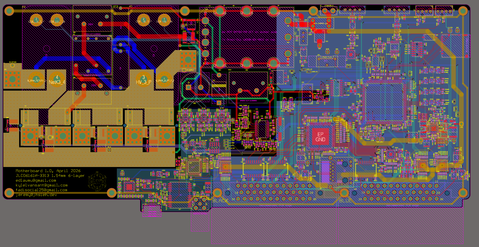
I contributed to the PCB layout and routing of the motherboard in Altium Designer, working within a dense mixed-signal design that combines low-voltage digital electronics, isolated high-voltage sensing, communication buses, power circuitry, and safety-critical control signals on a single board.